Thursday, 15 March 2012

Week 8

Title of the activity:  Test or troubleshoot the interfacing circuit between PIC circuit with Output circuit

Objective:
  • To know the circuit function properly
  • To troubleshoot when the circuit have a problem

Content/Procedure:
  • Burn the program into PIC circuit
  • Check the program related or not with PIC circuit
  • Adjust the functionality of program or calibrate the reference voltage ( Vref ) to ensure the actual temperature is equal with function in PIC
  • Interface the PIC circuit with output circuit
  • Check again and ensure the overall circuit working as expected and is same with simulate in proteus

Burn the program into PIC
  • For this project, at the PIC circuit I burn the program as directly and not use other out interface component because in software MPlab IDE have a PICkit2 software and just connected the wire from computer to PIC circuit but make sure at the PIC circuit have a pin IDC10 connector with PIC and it one of component from In Circuit Serial Programing ( ICSP )


Calibrate the reference voltage ( Vref )

Interface the PIC circuit with output circuit

Comparison real circuit function with simulate circuit function


Analysis:

For the analysis about this task, what can see at the above figure, student will burn the program into PIC circuit using normally method is using the interface software but for this project, it’s burn directly from computer to circuit. The important part is calibrate voltage reference ( Vref ) should have setting temperature is same with actual temperature and get the desired output as example; when setting temperature for speed 1 is 17°C to 21°C but if not calibrate Vref based on set point is not get the exact result for actual temperature probably swap with setting temperature.

Conclusion:

Circuit is working properly and knows how to burn the program into PIC, troubleshoot circuit also interfacing PIC circuit with Output circuit have done. So, in this task the objective is achieved.

Thursday, 8 March 2012

Week 7

Title of the activity: Construct and design overall circuit on the PCB board

Objective:
  • To design the interfacing circuit between PIC circuit and Output circuit
Content/Procedure:
  • Design circuit by using protel design system software
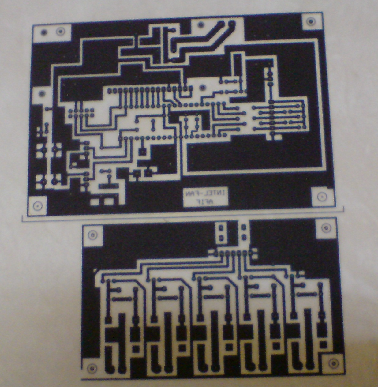
  • Print the design on the transparent paper or stick paper
  • Etching process
  • Drill and solder all component on the circuit

Protel Design System software

Design circuit
  • PIC circuit & Output circuit

    Print the design
    • PIC circuit & Output circuit

      Etching process
      • Step 1 : Remove material from such as unwanted copper from the PCB surface to achieve circuit design requirements.

        • Step 2 : Remove the black ink on the PCB board. The black ink has remove in order to solder the components

          Drill and solder all components on the circuit


          Analysis:

          While doing this circuit, the most important thing that must be take note is the actual design of the component. If the design is too small, the component cannot be match with the circuit. From the picture above, we can see on the circuit a lot of jumper. It is because, the connection of the circuit while doing etching method is disconnected and to joint it back, we use jumper and testing again with multimeter.

          Conclusion:

          The circuit is show the interface between PIC circuits with output circuit. While the design, construct on PCB board, etching process and soldering all the components have done, the next process is to testing the circuit which is the circuit is function properly based on expected. So, this part has done and the objective is achieved. 

          Thursday, 1 March 2012

          Week 6

          Title of the activity:  Run and simulate the programming of PIC in proteus

          Objective:
          • To ensure the circuit is working properly
          • To know the language program is connectively with the circuit

          Content/Procedure:
          • Use MPlab IDE software to write a language program
          • Check the language program
          • Compile the language program for ensure the language have error or not
          • Save the language program in save type assembly sources file
          • Run the language program in proteus
          • Check connection of the circuit

          MPlab IDE software

          Write the language program ( ASM language )

          Compile the language program
          • If have error, the software will display as below:

            • If the language is success


            Save the language

            Run the program in proteus
            Before run the program in proteus, selected properly file and processor clock frequency must check first. For the selected file, namefile.hex is used and processor clock frequency is selected depend on the PIC used.
            • PIC circuit

              Ø  When the LM 35DZ sensor has sense the environment temperature ( actual temperature ) at 17°C - 21°C, LED 1 is on. It is show the speed 1 of fan is run.
              o   PIC circuit

              o   Output circuit

              Ø  The running program is same with others speed ( speed 2 till speed 5 ) of fan


              Analysis:

              In this part, before run the program in proteus and it is call as simulate. Writing language in MPlab must do first, when compile done and if have error it means the something wrong at the language but sometime the compile has success and when run in proteus, nothing display. Probably, the connection of input and output port PIC not related with language program, so checking and try again must repeated.

              Conclusion:

              For this project, the circuit is run full of expected and working properly. So, the next task will proceed and in this activity, the objective is achieved.

              Thursday, 23 February 2012

              Week 5

              Title of the activity: Study programming of PIC 

              Objective:
              • To make the PIC operate
              • To study about language program ( ASM language )

              Content/Procedure:
              • Study and define pin of PIC
              • Study the ASM language
              • Discuss with programmer

              Pin i/o of PIC

              Define port :
              • Port A - sensor
              • Port B - LCD display
              • Port C / D – LED and connect to the output circuit

              Program language:
                              Assembly Language ( ASM )

              Continue till end program……………………

              Analysis:

              Based on this part, before write the program also run of project, many factor must taken such as refer to block diagram, flow chart of this project and must define the input and output ( i/o ) port of PIC. So, for this project the port of PIC has defined. Port A for sensor, Port B for display, Port C and D for Led. Beside, for language to write this program, assembly language has selected.

              Conclusion:

              For this project, this is difficult part and must study hard because if write the wrong program or wrong command, the circuit not function properly. After study with programmer and do the research about the language, the objective has done.

              Thursday, 16 February 2012

              Week 4

              Title of the project:  Construct the circuit using electronic software

              Objective: 
              • To select the which one of the electronic software
              • To construct the circuit of project

              Content/Procedure:
              • State the electronic software will use to design the circuit
              • Design the circuit in the software

              Proteus software

              PIC circuit

              Output circuit


              Analysis:

              For this part, much electronic software that use by engineering student for simulate their circuit such as Pspice, Multism, Proteus and etc. So, for this project, the proteus software has selected because in this project have a program and the proteus software has relevant compare with other electronic software. Beside, the main component that used is PIC, so it is already install in this software. Student should build all connection at the input and output pin at PIC. Circuit will design based on the block diagram refer step function. For the example at PIC 16F877A, it have Port A,B,C and D where each port have their own operation function. Student must define each port to make their operation based on the block diagram or planning.

              Conclusion:

              Using proteus software will help student understand to connect and design the circuit based on PIC performance.  In this work, connection between components is important to make circuit will operation smoothly when applying the program assembly language (ASM language). If the connection have a problem, this software will show where the connection wrong.

              Thursday, 9 February 2012

              Week 3

              Title of the activity:  Design structure circuit

              Objective: 
              • To know the design and construct of the circuit

              Content/Procedure:
              • Design the connection of the circuit
              • Discuss with lecturer

              PIC circuit


              Output circuit


              Analysis:

              Before do the simulation on the electronic software, sketch the connection of the circuit on the paper must take first. The figure below show the design of PIC circuit and output circuit:

              Conclusion:

              Design the structure circuit is a main part before design the real circuit because to ensure the project work properly also know the direction of wiring between components and combination of both circuit. So, in this part, the objective is achieved.

              Thursday, 2 February 2012

              Week 2

              Title of the activity:  List of component

              Objective:
              • To know the main component that use in the circuit

              Content/Procedure:
              • Analyze the suitable component use in the circuit
              • Find the component at the electronic and electrical shop 
              Figure 1 : List components
              Analysis:

              After the research about the component has done, it is time to get the component at the electronic and electrical shop such as shop at Jalan Pasar. The table below show the list of component will use in this project.


              Conclusion:

              List of component it is important part for ensure the component will used is complete and no missing part also to avoid waste of money. So, in this part the objective is achieved.