Thursday, 12 April 2012

Week 12


Title of the activity:  Design the poster for presentation day

Objective:
  • To design a poster about the whole project description to make people clearly about the project

Content/Procedure:
  • Explain the description of the project
  • Clearly the main objective
  • Design the block diagram
  • Methodology about the project
  • Make a result and analysis
  • Conclusion about this project
  • Poster design

Explain the description of the project
Ø  Intelligent ceiling fan controller based on temperature is the ceiling fan works with a speed control that automatically adjust the speed level due to the surrounding temperature without user have to select interested speed at the switch centrifugal. The speed fan is proportional to the temperature. As the temperature increase, the speed fan will be increased and vice versa

Clearly the main objective
Ø  To design an automatic controller circuits via combination of software (Proteus) and hardware
Ø  To understand the operation of speed control system for a ceiling fan application
Ø  To evaluate the functionality of the ceiling fan controller by considering the relationship of the speed change and room temperature

Design the block diagram

Methodology about the project
Ø  The system design is represented by a flow chart. The flow chart will explain on how the system works from the beginning to the end of the ‘intelligent fan’ process

Make a result and analysis


Conclusion about this project
Ø  Intelligent ceiling fan controller based on temperature is a user-friendly product. It senses the temperature and automatically adjusts the speed of the fan. The ceiling fan controller that built by using microcontroller chip PIC16F877A is really reliable and inexpensive to the end user

Poster design

Analysis:

From the poster it will describe everything about the project. The assessor can understand about the project from the poster. Methodology is explained how the whole of project function till end process. Block diagram can explain more clearly based on the block show. The block diagram shows the input and the output from the PIC. From the result it will display combination between software (proteus) with hardware part and the relationship between room temperature with speed of ceiling fan. The conclusion is concluding about the whole project.

Conclusion:

As a conclusion the poster is the most important thing to describe about the project. When the assessor and other reader read all the data and information on the poster it will give them satisfaction and just ask when they don’t know certain about the project.

Thursday, 5 April 2012

Week 11


Title of the activity:  Compile/get the result

Objective:
  • To obtain this project working based on expected
  • To ensure the project is follow the main objective of this project or not

Content/Procedure:
  • Understand the main objective
  • Get the result based on objective

The main objective
  • To design an automatic controller circuits via combination of software (Proteus) and hardware
  • To understand the operation of speed control system for a ceiling fan application.
  • To evaluate the functionality of the ceiling fan controller by considering the relationship of the speed change and room temperature.

Result based on objective
  • Compare the result between in proteus with hardware part
Ø  Speed1
   
Ø  Speed2

Ø  Speed3

Ø  Speed4

Ø  Speed5

  • Operation of speed control system for a ceiling fan application
Ø  Ceiling fan usually using single phase AC induction motor
o   Split-phase permanent capacitor
o   Capacitor start, capacitor run
o   Shaded pole motor

Ø  Motors have windings wound for 18, 20 or 22 poles, resulting in to lower operating speeds (Most common: 18 pole)

Ø  The rotor resistance is very high for wide speed control range using the stator voltage control

Ø  The operating speed range for the ceiling fans are
o   180 rpm to 380 rpm for countries like India
o   110 rpm to 220 rpm for Developed World
o   Low Speed is approx. half of high speed

Ø  Between low and high speeds three to five operating speed at equal interval is achieved using the variable speed control.

  • Relationship of the speed change and room temperature
Ø  Based on theory, the speed fan is proportional to the changers of the temperature. So, to prove whether the theory true or not, the speed of ceiling fan of this project must taken when the temperature is change. The value of rpm of ceiling fan has taken using tachometer and represented in graph form.

Analysis:

For the analysis, comparison between software (proteus) and hardware part is tally with other, when the actual temperature in proteus display for speed1 18°C and select the relay1, same like at the hardware part is do the same task. Beside, relationship between room temperature with speed of ceiling fan is proportional, when the temperature increase, the speed fan also increases

Conclusion:

As a conclusion, the main objective of this project is achieved when proved by taken the result of this project, also the objective in this task is achieved.

Thursday, 29 March 2012

Week 10

Title of the project:  Run the project

Objective:
  • To ensure the circuit is working properly when combined with hardware part
  • To study about wiring / connection output circuit with AC load and AC power supply

Content/Procedure:
  • Check the connection overall circuit with AC load and AC power supply
  • Turn On the switch and run the project

Connection overall circuit with AC load and AC power supply
  • In this part, correctly wiring is important. Neutral wire for AC load and neutral wire for AC power supply is connect with output circuit

    Run the project


    Analysis:

    For the analysis in this task, the important note is how connection the output circuits with AC load and AC power supply. If wrong connection the circuit probably the component burn and if the projector touch the circuit, it feel some electric shock so to avoid this thing, exact connection must be applied.

    Conclusion:

    As a conclusion, the project is working properly when the overall part is connected and full of the expected. So, this objective is achieved.

    Thursday, 22 March 2012

    Week 9

    Title of the activity:  Design hardware and mechanical part

    Objective:
    • To build hardware for this project
    • To ensure the hardware and mechanical part suitable with circuit

    Content/Procedure:
    • Design the suitable part
    • Used the suitable instrument to build this hardware
    • Arrange the overall part

    Design the suitable part
    • Build the rectangular transparent box for location of circuit

      • Build the stand for ceiling fan

        Used the suitable instrument

        Arrange the overall part


        Analysis and Conclusion:

        This hardware is suitable for this project and the portable hardware. It is design is look simple and more design can diversify. The design is look like that because to cut the cost and not waste the money. 

        Thursday, 15 March 2012

        Week 8

        Title of the activity:  Test or troubleshoot the interfacing circuit between PIC circuit with Output circuit

        Objective:
        • To know the circuit function properly
        • To troubleshoot when the circuit have a problem

        Content/Procedure:
        • Burn the program into PIC circuit
        • Check the program related or not with PIC circuit
        • Adjust the functionality of program or calibrate the reference voltage ( Vref ) to ensure the actual temperature is equal with function in PIC
        • Interface the PIC circuit with output circuit
        • Check again and ensure the overall circuit working as expected and is same with simulate in proteus

        Burn the program into PIC
        • For this project, at the PIC circuit I burn the program as directly and not use other out interface component because in software MPlab IDE have a PICkit2 software and just connected the wire from computer to PIC circuit but make sure at the PIC circuit have a pin IDC10 connector with PIC and it one of component from In Circuit Serial Programing ( ICSP )


        Calibrate the reference voltage ( Vref )

        Interface the PIC circuit with output circuit

        Comparison real circuit function with simulate circuit function


        Analysis:

        For the analysis about this task, what can see at the above figure, student will burn the program into PIC circuit using normally method is using the interface software but for this project, it’s burn directly from computer to circuit. The important part is calibrate voltage reference ( Vref ) should have setting temperature is same with actual temperature and get the desired output as example; when setting temperature for speed 1 is 17°C to 21°C but if not calibrate Vref based on set point is not get the exact result for actual temperature probably swap with setting temperature.

        Conclusion:

        Circuit is working properly and knows how to burn the program into PIC, troubleshoot circuit also interfacing PIC circuit with Output circuit have done. So, in this task the objective is achieved.

        Thursday, 8 March 2012

        Week 7

        Title of the activity: Construct and design overall circuit on the PCB board

        Objective:
        • To design the interfacing circuit between PIC circuit and Output circuit
        Content/Procedure:
        • Design circuit by using protel design system software
        • Print the design on the transparent paper or stick paper
        • Etching process
        • Drill and solder all component on the circuit

        Protel Design System software

        Design circuit
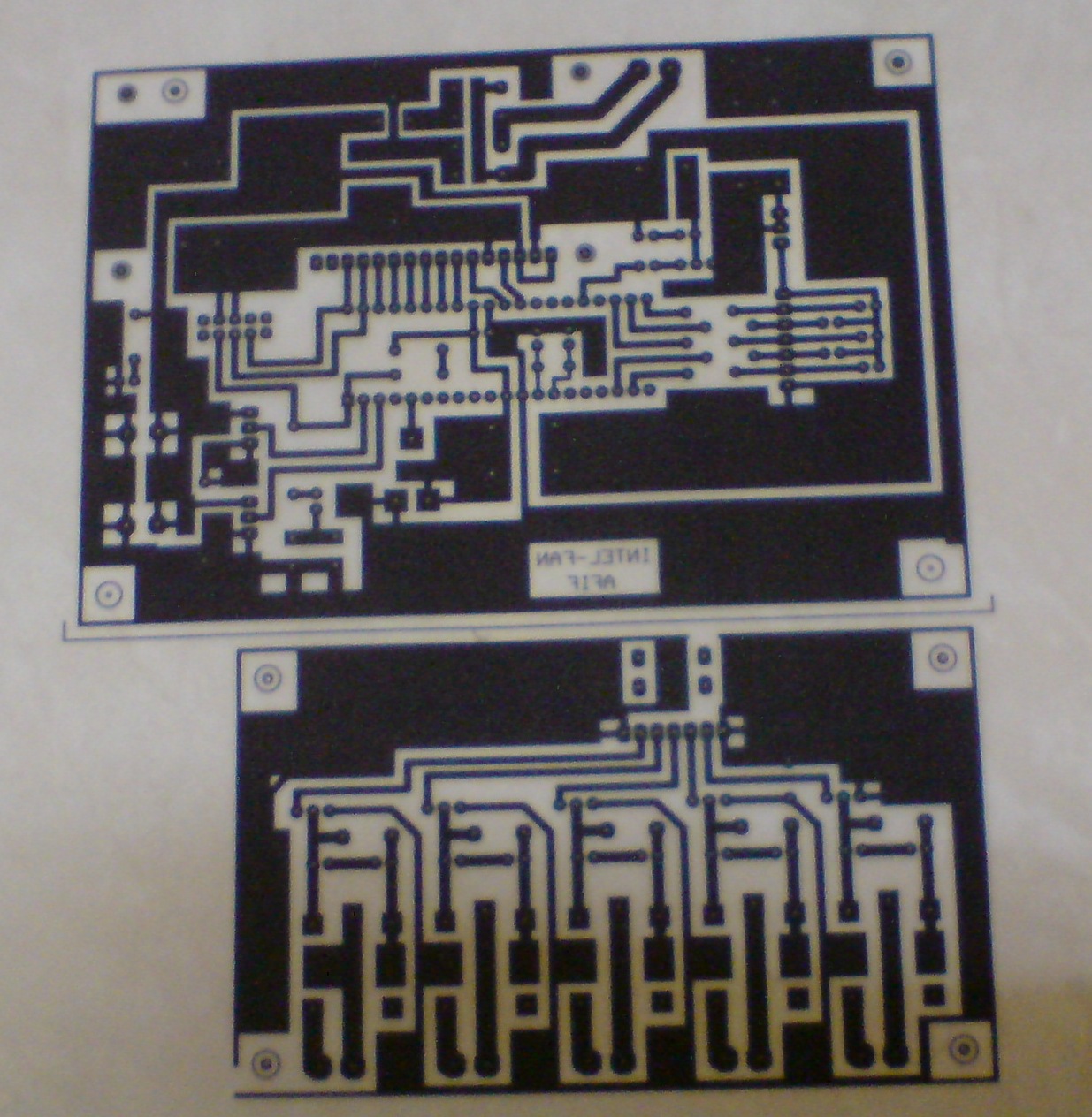
        • PIC circuit & Output circuit

          Print the design
          • PIC circuit & Output circuit

            Etching process
            • Step 1 : Remove material from such as unwanted copper from the PCB surface to achieve circuit design requirements.

              • Step 2 : Remove the black ink on the PCB board. The black ink has remove in order to solder the components

                Drill and solder all components on the circuit


                Analysis:

                While doing this circuit, the most important thing that must be take note is the actual design of the component. If the design is too small, the component cannot be match with the circuit. From the picture above, we can see on the circuit a lot of jumper. It is because, the connection of the circuit while doing etching method is disconnected and to joint it back, we use jumper and testing again with multimeter.

                Conclusion:

                The circuit is show the interface between PIC circuits with output circuit. While the design, construct on PCB board, etching process and soldering all the components have done, the next process is to testing the circuit which is the circuit is function properly based on expected. So, this part has done and the objective is achieved. 

                Thursday, 1 March 2012

                Week 6

                Title of the activity:  Run and simulate the programming of PIC in proteus

                Objective:
                • To ensure the circuit is working properly
                • To know the language program is connectively with the circuit

                Content/Procedure:
                • Use MPlab IDE software to write a language program
                • Check the language program
                • Compile the language program for ensure the language have error or not
                • Save the language program in save type assembly sources file
                • Run the language program in proteus
                • Check connection of the circuit

                MPlab IDE software

                Write the language program ( ASM language )

                Compile the language program
                • If have error, the software will display as below:

                  • If the language is success


                  Save the language

                  Run the program in proteus
                  Before run the program in proteus, selected properly file and processor clock frequency must check first. For the selected file, namefile.hex is used and processor clock frequency is selected depend on the PIC used.
                  • PIC circuit

                    Ø  When the LM 35DZ sensor has sense the environment temperature ( actual temperature ) at 17°C - 21°C, LED 1 is on. It is show the speed 1 of fan is run.
                    o   PIC circuit

                    o   Output circuit

                    Ø  The running program is same with others speed ( speed 2 till speed 5 ) of fan


                    Analysis:

                    In this part, before run the program in proteus and it is call as simulate. Writing language in MPlab must do first, when compile done and if have error it means the something wrong at the language but sometime the compile has success and when run in proteus, nothing display. Probably, the connection of input and output port PIC not related with language program, so checking and try again must repeated.

                    Conclusion:

                    For this project, the circuit is run full of expected and working properly. So, the next task will proceed and in this activity, the objective is achieved.